Therefore the physical separation between three phases ( water, oil, and gas) is one of the basic production, processing, and treatment in oil and gas facilities.
Separator where mainly designed for mechanically separate liquid hydrocarbon and gases at specific temperature and pressure.
Proper design for separator ( including the instrumentation) is important because separation vessel is normally the initial processing vessel at any facilities.
EQUIPMENT DESCRIPTION

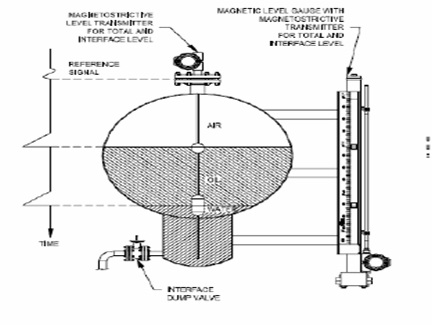
The fluid enters the separator and hits an inlet diverter causing a sudden change in momentum. The force of gravity causes the liquid droplets to fall out of the gas stream to the bottom of the vessel and separate liquid and vapor . This force the liquid (mixture of oil and water) to mix with the water continuous phase in the bottom of the vessel and rise through the oil water interface.
The liquid collecting section of the vessel provides sufficient time so that the oil and emulsion form a layer or “ oil pad “ at the top, and water settles to the bottom. To control the oil and water interface level. The level of the water is controlled by level controller that operates the water dump valve. The oil is skimmed over the weir and the level of the oil downstream of the weir is controlled by level controller that operates the oil dump valve.The usefulness of a level controller depends solely on the ability to detect and control it.
FLUID INTERFACE LEVEL MEASUREMENT
Magnetrostictive (usually with magnetic level gauge), guided wave radar, displacer and differential pressure level transmitter are among the most common technologies used to measure a liquid interface (such as oil and water) level. However variable process condition can effect the reability of each device. Changing specific gravities, dielectric constant, present emulsion layer and vapour layer must be taken into consideration when deciding upon a technology. The reability of the chosen instrument will be based on how well the users trust the device and information obtained from it.
OPERATING PRINCIPLE
Guided wave radar

Guided wave radar utilizes an antenna inserted into process to focus microwave energy from a transmitter. The transmitter measures the time of flight from the pulse to a returned from a dielectric. The dielectric of the product will dictate the amount of energy that is reflected. A low dielectric material such as oil, will reflect some amount of energy and allowing the rest to pass through it. While high dielecric material will reflect the majority of the energy.
In an interface measurement. The speed of the energy that passes through the lower dielectric liquid will decreased proportionally.
Displacer Level Transmitter

Changing process liquid level will causes the displacer element. Which is supported by a spring. To rise and fall. An armature, located in the pressure tube of the head, is directly linked to the displacer and move vertically with the displacer element. In the enclosure, linear variable differential transformer provides an output proportional to the position of the armature.
The displacer length is determined by the operating range specified, specific gravity, pressure, and temperature of the process.
Differential pressure level transmitter
The basic measurement of differential pressure level transmitter is pressure proportional to level. The head pressure of the liquid corresponds to its height multipled by the specific gravity.
When the process is corrosive, contains solid, or the process temperature outside the operating limit. Transmitter with remote seals is recommended so that the transmitter can be removed from direct contact with the process fluid.
CALIBRATION AND COMMISSIONING
Magnetostrictive
Magnetostrictive is by far the most “user friendly: when it comes to commissioning. The main calibrator is done by the supplier who designs the float for certain specific gravity interface, setting the output can be done by the use of an integral keypad and onboard display or through a HART communicator. The user simple select the range and inputs the values. Moving the float up or down by hand (or magnet) of by manipulating the liquid level can be used ti verify the transmitter’s operation.
Guided Wave Radar
The range values of guided wave radar can be set just like Mangnetostrictive, but if the dielectric constant of the upper fluid is not known, the user will have to raise and lower the interface level to set the range values.
Displacer Level Transmitter
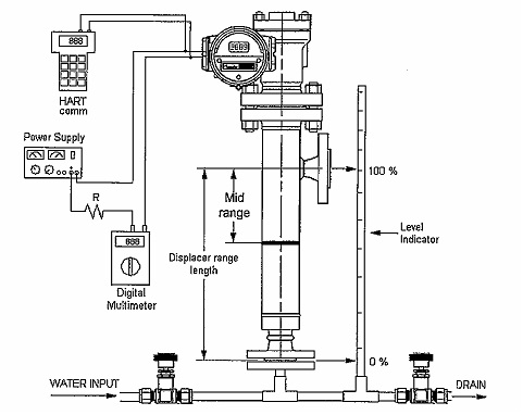
For Total MeasurementIf calibration by water multiply the distance between low connection and high
connection by the SG specified in data sheet, this give the 100 % level to be used
with water.
Low SG = 0.8
Supposing the level is A 14” size the SG is the 100 % level will be 14” X 0.8 =
11,2 “
0 % = Empty level
50 % = 11.2/2 = 5.”6
100 % = 11.2 “
For Interface Measurement
Low SG = 0.8
High SG = 1
Supposing the level is A 14” size = 355.6 mm
Principle: 0% = Full of liquid of low SG
100% = Full of liquid of high SG
Determine the 0% level : 355.6 x 0.8 = 284.48 mm
100% level : 355.6 x 1 = 355.60 mm
50% level : (355.6 – 284.48)/2 + 284.48 = 320.04 mm
DP Level transmitter
Example:
using two seal system in closed tank as shown below
The calibrated span set points are:
4 mA = Lmin S – hSf
= -99 in H2O
20 mA = LmaxS – hSf
= -45 in H2O
EFFECT OF PROCESS (EMULSIONS)
In a production environment, the action of the process will create an emulsion betweeb the layers of an interface. For a transmitter, the process will appear as three layers of liquid with two interfaces. The emulsion layer, will have its own specific gravity and dielectic constant. The extra layer affect tansmitter differently.
A magnetostrictive and displacer transmitter will give an output based on the position of the float used. When an emulsion is created the float will act as id the specific gravity become denser and rise higher in the process and will give certain amount of error on reading.
Guided wave radar does not respond well when an emulsion is present, Due to the emulsion has its own dielectric. The time of flight will change through this layer similar to the change experienced through the lower dielectric value and since the electric value is not known and vary. The energy passing through the emulsion may results interface reading lower than the actual level. High pressure inside the vessel can also change the fluid property and result “spike” on the measurement value and result spurious shutdown to the facilities.
DP Level transmitter measure the upper and lower pressure of the liquid in the vessel and multiplied it by the specific gravity. If the emulsion present, the specific gravity need to be adjusted and zero and span value need to be re-adjust as per actual liquid in the vessel.
Conclusion
Guided wave radar is not the most reliable for Interface level measurement. Magnetostrictive and Displacer give better accuracy, ease of operation and reaction to the process. DP transmitter need to be adjusted to the actual liquid present on the vessel but more stable and the emulsion layer will not give significant difference to the output.
References:
Maurice Steward , Surface production operation
Rosemount catalogue
Clark reliance Displacer Catalogue
Various sources on internet
M Iqbal M, when not jogging on hills or riding motorcycle,
is an instrument engineer that had been working in several
oil and gas projects. He obtain his B.Sc. From
Institut Teknologi Bandung (ITB). Indonesia in 2006.
He lives in Bandung with his family.
I like the valuable info you provide on your articles. I’ll bookmark your blog and check again right here regularly. I’m quite certain I will be informed a lot of new stuff right here! Good luck for the next!Gas Flow Meter: GFM100.
ReplyDelete