If the valve is sized incorrectly and the valve needs to be changed, everybody will know it. And it is hard to change it insitu, not including how to perform the seat leak test when the valve had been changed.
Instrument Society of America’s method (ISA S75.01 “Control Valve Sizing Equations) can be used for calculating the sizing coefficient
As per the Flow chart, Control valve is sized by Calculating the flow coefficient (Cv)
For liquid service, ISA’s standard (ISA S75.01 “Control Valve Sizing Equations) is used.
Liquid Service with Turbulent liquid flow (including flashing service)

Liquid with Specific gravity of 0.5 is flowing through a control valve at the rate of 33 m3/h, inlet pressure of 33.1 kg/cm2G and outlet pressure 31.5 kg/cm2G. Calculate the flow coefficient assign vapour pressure of 20.2 kg/cm2A and critical pressure of 43.3 kg/cm2A
Assume single seat globe valve with reducer; CFR = 0.8 , R = 1, CF R/ R = 0.84, KC (Coefficient of incipient cavitation ) = 0.58
P = (33.1 + 1.03) – (31.5 + 1.03) = 1.6 kg/cm2
PS = P1 - ( 0.96 – 0.28Pv = (33.1+1.03)-( 0.96 – 0.28 ) 20.2
= 18.60 kg/cm2
Flow is sub critical, since P = 1.6 > (FLP/ FP) 2 ( Ps) = (0.94) 2 (18.6) = 16.4 kg/cm2
Cv = (1.17)(33) = 17.06 without reducer correction
Hence, Cv = (20.4)/(0.96) = 17.77 with reducer correction
Liquid Service with Laminar liquid flow
If viscosity of upstream is higher than 10cP, viscosity compensation is necessary
Reynold numbers factor ( need to be included on calculation.
Cv = (1.17 q/ FR ) (GF /∆P)
Rev = 76000q/ (VCv )
FR can be find from the table below

Gas and Steam Service
Where :
Z = Compressibilityfactor
W = Flow rate (kg/h)
T = Flowing temperature (C)
Two Phase Service
In cases where liquid and its vapor are entering the valve, use the liquid with and average density of liquid and vapor
Control valve Selection
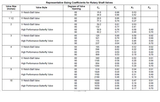
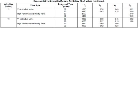
From the calculated Cv control valve bodies and type can be determined . Fisher catalog can be use as an example shows below

For the port size selection Cv. The percentage of travel shall meet the condition below
EQ % LINEAR
At max Flow Rate < 95% < 90%
At Nor Flow Rate < 85% < 60%
At min Flow Rate >10% > 5%
References:
1. Fisher “Control Valve Handbook”
No comments:
Post a Comment