Reason for using orifice (DP flow transmitter)
Simple (but they are hard to install to get a good velocity profile)
Inexpensive (well there are cheap ultrasonic flowmeters with better accuracy and turndown ratio than DP transmitter today)
Available in various sizes, type, and connections.
Simple design, rugged, and suitable for liquids, gases, steam.
Reason for not using orifice (DP flow transmitter)
Low down turn ratio, typically 3:1 with accuracy not exceed than +/- 1%
Sensitive for flow profile (next time if the process engineer ask why the flow measurement inaccurate, tell them with the flow profile is laminar and the reynolds number is insufficient)
The process fluid is in the impulse lines to the differential transmitter may freeze or block (plug)
Component of a typical orifice metering loop are:
- Orifice plate and holder
- Orifice taps
- Differential pressure transmitter
- Flow controller
Orifice Plates
Orifice consist of a flat size of metal with sized holed bored in to it. When fluid through the orifice its velocity increases, resulting a drop in pressure and an increase in turbulence. After the fluid has passed
through the orifice its velocity decreases again, causing an increase in pressure although only
some of the pressure loss is recovered. The amount of pressure recovery can be up to 50% of
the total pressure drop across the orifice plate
The most critical part of the meter is the orifice plate. The most known standards to define the plate’s edge, flatness, thickness, bevel details and bore limitation are AGA-3 and ISO 5167-1

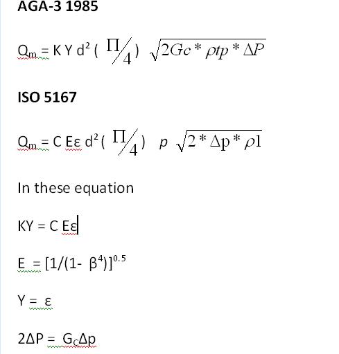
Qm = mass flow rate (SCF/hr)
C = Orifice coefficient of discharge (dimensionless), empirically determined in the standards and it depends on the plate and meter run size
E = Velocity of approach factor (dimensionless),, corrects for the change in the flow constriction shape with various beta ratio plates
Y = Expansion Factor (dimensionless), Correct for the change in density from the pressure tap to the orifice bore in gas measurement.Its value is a function of the beta ration, differential pressure, static pressure at the designated tap
∏ = 3.14159, used to convert the orifice diameter to area
d = orifice plate bore diameter calculated at flowing temperature Tf (inch)
GC = Dimensional conversion constant
ρtp = density of the fluid at flowing condition (Pf, Tf)
∆P = orifice differential pressure (psia) measured across the orifice
The most important variable in the equation is the differential pressure, there fore a major effort should be made to have as high as possible. The second one is the flowing density. It have to be measured or calculated from appropriate equations.
Sizing an orifice depends on the flow measurement task to be done. A simple design would be a single meter tube with single oprifice plate in the mid beta ratio range, if the flows grows overtime 0.2 beta plate can be used and if the flow is decrease with time then a large beta (suc as 0.6) should be used.
References:
1. ISA Practical Guides for Measurement and Control, Friedmann.p, Stoltenberg.T
2. ISO 5167-2 and AGA-3
3. API MPMS 14.3.1&2 Orifice plate
4. Daniel orifice catalogue
Great Post..In general,differential pressure and bore dia must be known for orifice design..from where we can have an idea of differential pressure requirements based upon which orifice bore dia shall be decided??
ReplyDeletePrince Single: Back in the old days, DP range can be easily determined by using the same DP range in the Barton's Flow recorder's chart (0-100/150/200/250 inH2O). now most company have their own specification to determine it.
Deletethe following may be also used: 0-50,0-125, 0-250, or 0-500 mbar
Very significant Information for us, I have think the representation of this Information is actually superb one. This is my first visit to your site. Orifice Plate
ReplyDelete